Designing & Simulating CNC Toolpaths
At Wolf Composites, every precision mold begins as a vision in CAD. We start by importing a fully detailed 3D model into our SOLIDWORKS CAM environment, where our engineers begin the critical process of tool path generation. Each part is analyzed for geometry, surface accessibility, and fixturing constraints. We create a complete mach-
 ining strategy that includes roughing, semi-finishing, and final finishing operations—each tailored to the material, tool type, and geometry of the part. These toolpaths are not just estimated cuts; they’re rigorously simulated to ensure optimal tool engagement, proper chip evacuation, surface finish quality, and—most importantly—collision-free operation. By validating every step in the virtual world first, we reduce risk, eliminate waste, and ensure the machining process is as efficient and repeatable as possible
Exporting the Master Pattern

Once toolpath simulations are verified, we export a high-fidelity master pattern. This file contains the fully resolved 3D surface geometry that will drive the physical machining process. The master pattern represents every contour, draft angle, and fine feature needed to generate a production-grade mold. At this stage, tolerances are checked, fillet radii are reviewed, and material considerations are confirmed. This digital master serves as both a machining reference and a documentation standard—defining the exact dimensional intent of the final part.
Preparing the Glue‑Up Fixture

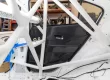
For large or multi-surface molds, we fabricate a precision glue-up block to serve as the machining substrate. This involves CNC-cutting and assembling multiple sheets of high-density tooling board—typically
polyurethane or epoxy-based—for dimensional stability and machinability. The board layers are aligned and bonded using industrial adhesives under pressure to prevent shifting, warping, or internal voids. Care is taken to orient seams and bonding lines to minimize stress during cutting. The result is a single, structurally sound block that mirrors the size and volume of the part to be machined, ready for mounting and rough cutting.
Rough Cutting & Bulk Material Removal

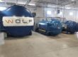
With the glue-up fixture mounted on our EMS 5-axis CNC machine, we begin the roughing phase. This step uses large-diameter, high-feed cutters designed to remove as much material as possible in the shortest time while maintaining rigidity and chip control. The machine follows a coarse toolpath that steps down through the block in layers, carving out the broad shape of the mold. Strategic stock patterns—such as step-overs and grooves—are left in place to retain structural integrity and prevent chatter during finishing. Though the rough cut doesn’t provide final detail, it sets the foundation for precision by establishing correct part volume, surface orientation, and datum alignment.
Final Finishing of the Master Pattern

Following the roughing operation, the CNC switches to smaller, fine-finishing tools capable of achieving tight tolerances and refined surface finishes. This pass is where the mold truly takes shape. Every curve, edge, and surface is machined to specification with careful attention to tool deflection, spindle speed, and material response. After cutting, the
part undergoes a meticulous post-process inspection. Our team manually deburrs, hand-sands, and inspects for any remaining imperfections, ensuring the master pattern meets both visual and dimensional standards. Any necessary touch-ups are performed to achieve a flawless mold-ready surface—one that ensures composite layups will bond cleanly and release consistently.